PourBot - Hacking the Kettle
I'm attempting to build an Arduino-powered coffee machine named PourBot.
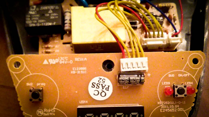
In the previous post, I decided on an electric kettle to heat the water to the ideal coffee brewing temperature ~195F. I cracked the Kettle's base station open and found two boards inside. One was connected to the heating element with thick, scary wires, the other had buttons, the temperature LED, and a microcontroller. They were connected by 5 wires:

To MacGyver this kettle for PourBot, I needed control over the heating element and the ability to read the water's temperature.
I had five unknown wires and a multimeter. Time to reverse engineer the wires' purposes!
If electronics are also new to you, this is how it feels to open an electronic device, plug it into the wall, and press buttons while trying to discover what the wires do:

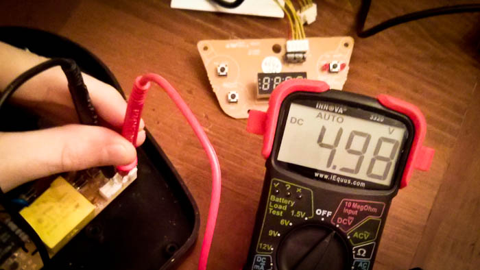
Reality looks more like this:

First discovery: the kettle's control electronics are regulated to 5V, which is what the Arduino operates with (and is pretty standard)! This means no extra work to communicate with the kettle, I can jump wires straight to the Arduino.

The Kettle's base has three states: without Kettle, idle, and on.
Without the Kettle, the LED does not display its temperature, so I started measuring the voltages over the wires in this state. From yellow-to-red, they were:
- 5V
- 0
- 0
- 2.5V
- 0 (Red)
I was off to a good start, finding the positive/anode wire #1. I was unsure of negative/cathode, somewhat expecting it to be the red wire #5, but it could also be wires #2 or #3. The 2.5v wire #4 was a mystery (and still is, tweet me @KrisJordan if you know the purpose it serves).
Next, I transitioned to the idle state by placing the kettle, with some room temperature water in it, on the base. Here were the voltages of the wires:
- 5V
- 0
- 0.37V
- 2.5V
- 0 (Red)
Ah ha! With the kettle on the base, wire #3 had a voltage. Given its fractional value, this must be the temperature sensor. If so, it should increase as the water heats up.
"Here we go," I winced while pressing the Boil button of the high-wattage electric kettle. Once I heard the heating element doing work, I took another reading of the wires while in the On state:
- 5V
- 0
- 0.84V
- 2.5V
- 5V (Red)
With the device on, the negative/ground/anode wire turned out to be #2. The red wire, #5, was a full 5V and clearly the wire controlling the relay to the heating element. Finally, an increasing voltage on the thermal sensor wire #3 confirmed it was rising with the temperature of the water.
Now we have a pin layout!
- Positive
- Negative (Ground)
- Thermal Sensor Output
- 2.5V(?)
- Power Relay Input (0 off, 5V on)
Mission accomplished: we can read the thermal sensor and control the heating element.
Next, I need to reverse engineer the output from the thermal sensor to know how to convert its voltage reading into degrees fahrenheit. Remember, 195°F is the target temperature for brewing coffee!
